- El-Genk, M.S., T. Schriener, Lightweight Heat Pipe Radiator for Nuclear Reactor Power Systems on Lunar Surface. J. Nuclear Technology, 2025. 211(3) 400-428
- Kresl-Hotz, K.R., El-Genk, M.S., Schriener, T.M., Numerical Mesh Refinement for Flow Mixing in Pool Type SFR. Proceedings ANS Student Conference 2025, 2025.
- Kresl-Hotz, K.R., El-Genk, M.S., Schriener, T.M., CFD Analyses of the Flow Mixing and Stratification in Pool Type SFR. Proceedings ANS Student Conference 2025, 2025.
- Schriener T.M., M.S. El-Genk, Armoring Lightweight Foldable Radiator Panel for Lunar Surface Fission Power Systems. J. Nuclear Technology, 2025. 1-25
- Schriener T.M., M.S. El-Genk, Launch Solid Stress Analyses of Ultra-Light Heat Rejection Radiator Module and Panel for Lunar Fission Surface Power. J. British Interplanetary Society, 2025. 78(3) 74-83
- El-Genk, M.S., T.M. Schriener, A.N. Shaheen, Machine-Learning Algorithms for Remote-Control and Autonomous Operation of the Very-Small, Long-Life, Modular (VSLLIM) Microreactor. J. Nuclear Engineering, 2025. 6(4) 54
- El-Genk, M.S., T.M. Schriener, Lightweight Heat Pipe Radiator for Nuclear Reactor Power Systems on Lunar Surface. Nuclear Technology, 2024. 1-29
- Schriener, T.M., M.S. El-Genk, Armored Lightweight Heat Rejection Radiator for Lunar Surface Nuclear Reactor Power Systems. Proceedings ANS 2024 Nuclear and Emerging technologies for Space (NETS 2024), 2024.
- El-Genk, M.S., T. Schriener, Lightweight Heat Pipe Radiator Panel for Lunar Surface Fission Power Systems. Proceedings AIAA ASCEND Conference, 2024.
- El-Genk, M.S., Designs of Space Nuclear Reactor Power Systems for the Avoidance of Single Point Failures, Launch Safety, and a Long Operation Life. Proceedings AIAA ASCEND Conference, 2024.
ISNPS Director Mohamed El-Genk invited to be Panelist at Opening Plenary of 2024 ANS Winter Conference and Expo
12/4/2024
El-Genk invited speaker at the Open Plenary Panel at ANS Winter Meeting, 17-21, 2024
12/9/2024
Masters Graduation - Ahmad Shaheen
Ferris Engineering Center
Room 1120
Mailing Address:
Institute for Space & Nuclear Power Studies
MSC01-1120
1 University of New Mexico
Albuquerque, NM 87131
Phone: 505.277.5442
Fax: 505.277.5433
Online: Contact Form
System Simulation and Transient Analysis
Here at ISNPS we use a wide variety of system simulation and transient analysis tools. Select from the list below to get a brief overview of some of the work we have done with that specific tool. PDF downloads (as shown on the webpage) are available for download as well for off-line viewing if desired.
- 1. HPTAM
- 2. UNM Heat Pipe Model (UNM-HP)
- 3. AMTEC Performance and Evaluation Analysis Model (APEAM)
- 4. DynMo
1. HPTAM
The Heat Pipe Transient Analysis Model "HPTAM" (Figure 28) was developed at UNM-ISNPS for simulating the transient and steady-state operation, as well as the startup from a frozen state of alkali-metal and low-temperature heat pipes [35-38]. Heat pipes are used in many space nuclear reactor power systems for transporting the reactor's thermal power to the converters (lithium or sodium heat pipes), transporting the waste heat from the cold side of the converters to the heat rejection radiator (sodium or potassium heat pipes), and/or for spreading the heat in finned radiator surfaces (potassium, rubidium or water radiator heat pipes). HPTAM has been the subject of continuous upgrade since the early nineties using experimental data for water, Na (Fig. 29), and lithium (Fig. 30) heat pipes.
The fully 2-dimensional and transient HPTAM model (Figure 28) uses the Darcy's extended flow equations to model the liquid flow in the porous wick and annular space, in conjunction with a fixed-grid, homogeneous enthalpy method to calculate the change of phase in these zones. HPTAM calculates the radius of curvature of the liquid meniscus in the surface pores of the wick, and couples the vapor and wick regions with appropriate momentum and enthalpy jump conditions, which allows HPTAM to predict the capillary limit, partial recession of liquid in the evaporator wick, and pooling of excess liquid in the vapor core. HPTAM also calculates the rates of sublimation of the frozen working fluid in the evaporator and resolidification in the adiabatic and condenser sections early during the startup from a frozen state, and simulates the free-molecule, transition, and continuum vapor flow regimes using the Dusty Gas Model.
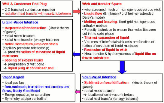
Figure 28. A Block-Diagram of the physical models Integrated into HPTAM for transient simulation of liquid-metal and water heat pipes, including the startup from a frozen state [35-37].
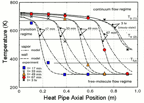
Figure 29. HPTAM's predictions of the axial distributions of wall and vapor temperatures during startup of a sodium heat pipe [36 ] (Data from Faghri et al., 1991).
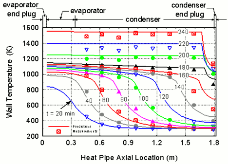
Figure 30. HPTAM's predictions of the wall temperature during startup of lithium heat pipe; symbols represent TC data at particular times [37] (data from Reid, Sena, Merrigan, Elder and Martinez 1999).
- 35. Tournier, J. -M. and M. S. El-Genk, "A Heat Pipe Transient Model," Int. J. Heat and Mass Transfer, 37(5), 1994, 753-762.
- 36. Tournier, J.-M. and M. S. El-Genk, "An Analysis of the Startup of a Radiatively-Cooled Sodium Heat Pipe from a Frozen State," AIChE Symp. Series - Heat Transfer, No. 301, 92, 1996, 324 - 332.
- 37. Tournier, J.-M., and M. S. El-Genk, "Startup of a horizontal Lithium-Molybdenum Heat Pipe from a Frozen Startup," International Journal of Heat and Mass Transfer, 46, 2003, 819 - 844.
- 38. El-Genk, M. S., L. Huang, and J. -M. Tournier, "Transient Experiments of an Inclined Copper-Water Heat Pipe," J. Thermophysics and Heat Transfer, 9(1), 1995, 109 - 116.
 Back to The Top
2. UNM Heat Pipe Model (UNM-HP)
The UNM-HP is a steady-state performance and optimization model of fully-thawed alkali liquid metals (K, Na, and Li) and water heat pipes. It calculates the vapor pressure losses in the various sections of the heat pipe (evaporator, adiabatic, and condenser), when vapor flow is dominated by friction rather than inertia forces (vapor Mach number less than 0.5). The calculated vapor pressure losses determine the temperature drop in the vapor core along the heat pipe. This temperature drop is added to the conduction temperature drops in the wall, liquid annulus, and the liquid saturated wick, both in the condenser and evaporator sections. The sum of these temperature drops gives the total temperature drop along the heat pipe. UNM-HP accounts for both the inertia and friction forces in the vapor flow, and the vapor remains saturated. This heat pipe model has been verified successfully using experimental data of the vapor temperature along a short sodium heat pipe (0.7 m) operated at different powers and Mach numbers up to 0.4 (Ivanovskii et al., 1982; see Figures 31a and 31b).
The UNM-HP model has been used successfully in the design and thermal analysis of the heat pipes-cooled nuclear reactors and heat rejection radiator panels of the HP-STMC and SAIRS power systems developed at UNM-ISNPS. In such designs, the local radial and axial vapor mass fluxes of working fluid in the heat pipe are calculated from the local energy balance, which accounts for the heat input to the evaporator section and the heat rejection along the condenser section. UNM-HP also accounts for the heat conduction in the C-C fins of the radiator heat pipes and calculates various heat pipes operation limits; namely, the viscous, sonic, capillary, entrainment, and incipient boiling, to determine the useful operation domain bound by these limits. Figures 32a and 32b compare the predictions of the UNM-HP model of the operation limits of the radiator heat pipes in SAIRS-C with those obtained using the widely used HTPIPE model, developed by Los Alamos National Laboratory (Woloshun et al., 1989).
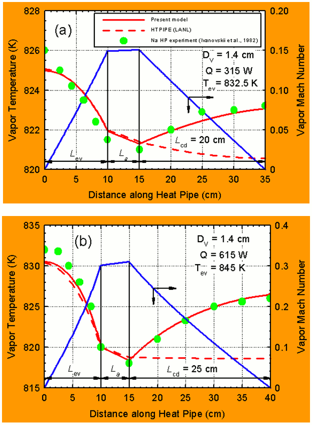
Figure 31. Comparison of UNM-HP predictions with measured vapor temperatures in a Sodium heat pipe at Mach numbers of 0.15 and 0.30 (Ivanovskii et al. 1982).
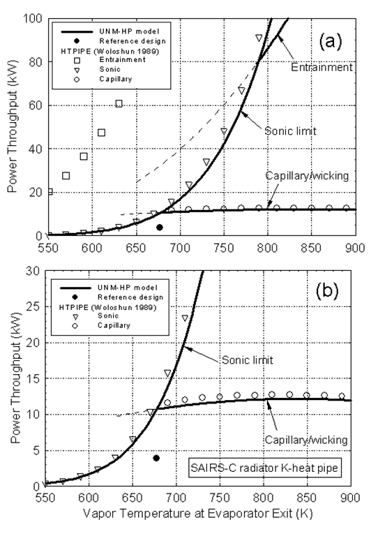
Figure 32. Operation limits of potassium heat pipe in SAIRS-C radiator.
Figures 32a and 32b shows predictions of the sonic and the capillary/wicking limits by the two models are in good agreement. Figure 33 shows the temperature contours of the SAIRS surfaces predicted by the model at nominal operation. The Scalable AMTEC Integrated Reactor Space Power Systems (SAIRS, Figure 26) developed at UNM-ISNPS all use D-shaped potassium heat pipes radiators with C-C armor and fins [32].
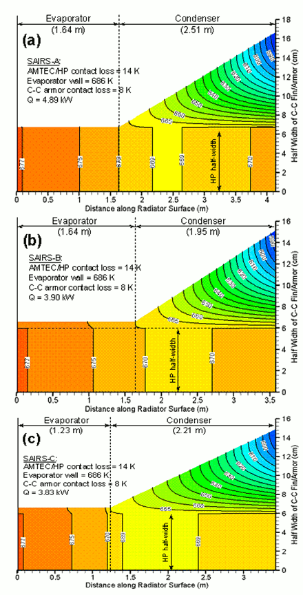
Figure 33. Surface temperature contours of SAIRS radiator C-C armor/fin.
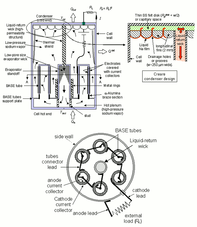
Figure 34. Cross-section views of a typical vapor anode AMTEC converter with 6 BASE tubes connected in series (not to scale).
 Back to The Top
3. AMTEC Performance and Evaluation Analysis Model (APEAM)
In the 1990's, UNM-ISNPS participated in a comprehensive testing and modeling program with the Air Force Research Laboratory's (AFRL) Space Vehicles Directorate. The objective of this program was to advance the technology of vapor anode, multi-tube Alkali-Metal Thermal-to-Electric Converters (AMTECs) for flight on future space missions. Each vapor anode, multi-tube PX-series AMTEC cell uses between 5 and 8 Beta''-Alumina Solid Electrolyte (BASE) tubes, connected electrically in series (Figure 34). The TiN or WRh anode and cathode porous electrodes are covered with molybdenum mesh current collectors, to minimize internal electric losses. A two-dimensional, integrated AMTEC Performance and Evaluation Analysis Model (APEAM) was developed at ISNPS, to support ongoing tests at AFRL and improve the design and performance of sodium and potassium PX-type AMTEC cells. This integrated cell model consists of four major components: (a) an alkali-metal vapor pressure loss model that calculates the low vapor pressure at the interfaces between the cathode electrode and the BASE tube. (b) a two-dimensional radiation/ conduction heat transfer model that accounts for all heat exchanges between the different components of the cell and calculates the temperatures throughout the cell (Figure 35). (c) a cell electrochemical model that calculates the effective potential developed across the BASE, due to the isothermal expansion of alkali metal ions. (d) two-dimensional electric circuit model that determines the electrical resistances of the BASE, electrodes, current collectors, and conductor leads to the external load, and calculates the cell's electrical potentials, electrode current density, and the cell's total electrical current. APEAM has been successfully benchmarked against experimental data of individual PX-type converters and of an eight-cell power generator ground demonstration that were electrically heated (Figure 36).
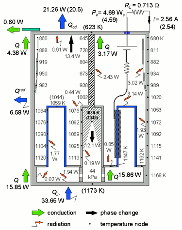
Figure 35. Predicted heat flow and structure temperatures in the PX-3A converter when operating at a peak electrical power of 4.7 We (experimental measurements are shown in parentheses).
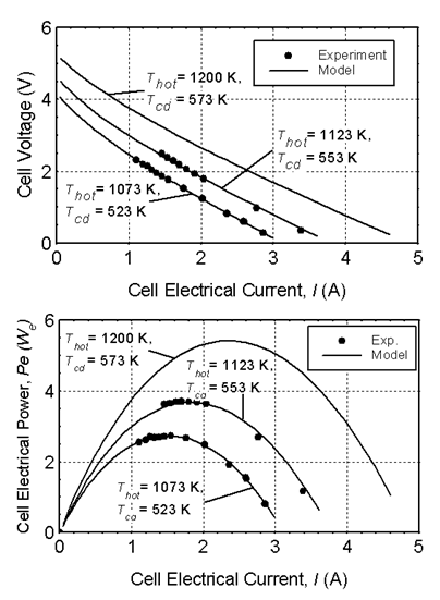
Figure 36. I-V characteristic and electric power output of PX-3G Cell #1 in Ground-Demo.
 Back to The Top
4. DynMo - TE
The ISNPS has developed, using the SIMULINK® platform, the Dynamic simulation Model (DynMo-TE) of Space Reactor Power Systems (SRPSs) that use a Sectored, Compact Reactor (SCoRe) designed for avoidance of a single point failure, and Thermo-Electric (TE) conversion (Figure 37). DynMo-TE (Figure 38) is comprised of a number of coupled physical models:
(a) The SCoRe Model couples a six-points kinetics model to a thermal-hydraulic model of the reactor core (Figure 38). The former calculates the reactor fission power, subject to the external reactivity insertion at a user specified rate and the temperature-reactivity feedback for the liquid lithium and UN fuel, and the Doppler reactivity feedback, when applicable. For long duration transient analysis DynMo-TE can account for reactivity loss due to fuel depletion.
(b) The Secondary and Primary Loop Models are coupled thermally in a PCA and a pumps' TCA (Figure 38); The coolant flow rates and pressure losses in the primary and secondary loops are calculated using the mass and momentum balance equations, at the points where the pressure loss demand-curves intersect the calculated pressure head supply-curves of the EM pumps.
(c) The Electro-Magnetic (EM) Pump Model calculates the pressure head supply-curve as functions of time and temperature, as function of the thermal and electrical resistivities of the duct wall material, coolant and copper buses, and the DC voltage and current supplied by the pumps TCA. The EM pumps use permanent magnets that are thermally insulated from the coolant ducts and maintained well below their Curie point. The magnet remains saturated by the secondary magnetic flux generated by the electric current passing through the pump ducts.
(d) The Radiator Panel Thermal-Hydraulic Model couples the 3 radiator segments (one forward and 2 in the rear) hydraulically in parallel (Figure 38), and discretizes the inlet and outlet flow channels of each segment into small axial sections. Each section comprises a small number (5 or 6) of rubidium heat pipes with C-C armor and C-C fins, and solves the coupled momentum and energy balance equations for the coolant flow rate and temperature. This model also calculates the temperature drops in the channel walls and the structure of the evaporator section of the heat pipes. The radiator model is coupled to a heat pipe model, to calculate the vapor flow and temperature drops in the heat pipes walls and C-C fins. The heat pipe model also calculates the sonic, capillary, entrainment, and incipient boiling limits.
(e) The Power Conversion Assembly (PCA) and Pumps TE Converter Assembly (TCA) Models both use a transient performance and optimization model of the SiGe unicouples. This model is also capable of predicting the performance of segmented TEs, with up to 3 different materials in each leg.
(f) Accumulator Model: To accommodate the volume changes in the liquid metal coolant in the secondary and primary loops during transient operation, each loop is equipped with a bellow type accumulator (Figure 38). The accumulator model accounts for the stiffness of the bellows, in addition to that of the compression spring. For operation redundancy, the cavity above the bellows is filled with inert gas to support the spring and the bellows in adjusting the coolant pressure in the loops. The accumulator model calculates the transient changes in the coolant volume in the accumulator, the compression length of the helical spring, and the coolant pressure in the loop.
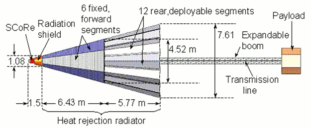
Figure 37. A layout of SCoRe-TE Space Nuclear Reactor Power System.
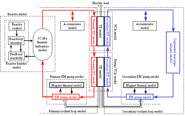
Figure 38. DynMo-TE for dynamic simulation of SCoRe-TE Space Reactor Power System (SRPS).
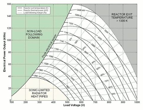
Figure 39. Steady-state operation map of SCoRe-TE, Space Reactor Power System.
DynMo-TE has been used successfully to optimize the design of the SRPS, investigate the effect of using different combinations of alkali metal coolants (Li, Na, and NaK) in the primary and secondary loops, study the startup transient and propose a startup scenario to minimize the amount of startup batteries needed, and investigate the load-following operation of the SRPS (Figure 39). DynMo-TE is particularly well suited for developing safe startup procedures and schemes for adaptive and autonomous operation and control of the SRPS.
DynMo - CBC
The ISNPS is currently developing, using the SIMULINK® platform, the Dynamic simulation Model (DynMo-CBC) of Space Reactor Power Systems (SRPSs) that use a gas-cooled reactor designed for avoidance of a single point failure, and Closed Brayton Cycle (CBC) engines (Figure 40). This model shares many of the same characteristics as DynMo-TE. Figure 40 presents the layout and the nominal full-power performance parameters of a typical SRPS with 3 CBC loops. The sectored, fission reactor, cooled with He-Xe, a Pellet Bed Reactor (PeBR) or Submersion-Subcritical Safe Space (S^4) reactor, is divided into three identical sectors loaded with nuclear fuel elements. These sectors are neutronically and thermally coupled, but hydraulically decoupled. Each reactor sector provides thermal power to a CBC loop with a single-shaft radial-flow Compressor-Generator-Turbine unit, a recuperator and a gas cooler. The gas coolers in the three CBC loops heat up the molten NaK-78 in the secondary loops, which transport the waste heat to water heat pipes radiator panels. The panels, two per CBC loop, are hydraulically coupled in parallel to reduce pressure losses. The water heat pipes have carbon-carbon (C-C) fins to extend the surface area for heat rejection, and C-C armor to protect against the impact of meteoroids. The NaK-78 in the secondary loops of the radiator panels is circulated using Alternative Linear Induction Pumps (ALIPs). The operating parameters of the CBC engines presented in Figure 40 account for the mechanical losses in the bearings, the electrical losses in the alternator windings, and the electromagnetic electrical losses in the electrical generator.
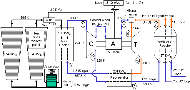
Figure 40. DynMo-CBC for dynamic simulation of multiple-loop Brayton SRPS.
The system layout in Figure 40, with a sectored nuclear reactor core, avoids single point failures both in reactor cooling and energy conversion. With a failure of one of the CBC engines, a loss-of-cooling, or a break in one of the primary gas loops, the present space nuclear power system continues to operate with two CBC engines, but at reduced electrical and reactor thermal powers. The fission power generated in the reactor sector of the failed CBC loop is transported by conduction and / or by thermal radiation to the dividers between the sectors and removed by forced convection to the circulating gas in the two adjacent sectors. DynMo-CBC will be useful for optimizing the design of the SRPS, studying the startup transient, investigating the load-following operation of the SRPS, and developing safe startup procedures and schemes for adaptive and autonomous operation and control of the SRPS.
 Back to The Top


