
- El-Genk, M.S., T. Schriener, Lightweight Heat Pipe Radiator for Nuclear Reactor Power Systems on Lunar Surface. J. Nuclear Technology, 2025. 211(3) 400-428
- Kresl-Hotz, K.R., El-Genk, M.S., Schriener, T.M., Numerical Mesh Refinement for Flow Mixing in Pool Type SFR. Proceedings ANS Student Conference 2025, 2025.
- Kresl-Hotz, K.R., El-Genk, M.S., Schriener, T.M., CFD Analyses of the Flow Mixing and Stratification in Pool Type SFR. Proceedings ANS Student Conference 2025, 2025.
- El-Genk, M.S., T.M. Schriener, Lightweight Heat Pipe Radiator for Nuclear Reactor Power Systems on Lunar Surface. Nuclear Technology, 2024. 1-29
- Schriener, T.M., M.S. El-Genk, Armored Lightweight Heat Rejection Radiator for Lunar Surface Nuclear Reactor Power Systems. Proceedings ANS 2024 Nuclear and Emerging technologies for Space (NETS 2024), 2024.
- El-Genk, M.S., T. Schriener, Lightweight Heat Pipe Radiator Panel for Lunar Surface Fission Power Systems. Proceedings AIAA ASCEND Conference, 2024.
- El-Genk, M.S., Designs of Space Nuclear Reactor Power Systems for the Avoidance of Single Point Failures, Launch Safety, and a Long Operation Life. Proceedings AIAA ASCEND Conference, 2024.
- El-Genk, M.S, T.M. Schriener, R. Altamimi, A. Hahn, Pumping Options for Versatile Test Reactor Molten Lead In-pile Test Cartridge. J. Nuclear Science and Engineering, 2023. 197 3082-3109
- Altamimi, R., M.S. El-Genk, Equivalent Circuit Model for Predicting the Performance Characteristics of Direct Current-Electromagnetic Pumps. J Material Sciences and Engineering, 2023. 12(1) 629
- Altamimi, R., M.S. El-Genk, Miniature DC Electromagnetic Pumps of Molten Lead and Sodium to Support Development of Gen-IV Nuclear Reactors. J Nuclear Engineering and Design, 2023. 410 112376
ISNPS Director Mohamed El-Genk invited to be Panelist at Opening Plenary of 2024 ANS Winter Conference and Expo
12/4/2024
El-Genk invited speaker at the Open Plenary Panel at ANS Winter Meeting, 17-21, 2024
12/9/2024
Masters Graduation - Ahmad Shaheen
Ferris Engineering Center
Room 1120
Mailing Address:
Institute for Space & Nuclear Power Studies
MSC01-1120
1 University of New Mexico
Albuquerque, NM 87131
Phone: 505.277.5442
Fax: 505.277.5433
Online: Contact Form
CFD Analysis and Simulation
Here at ISNPS we use a wide variety of computational fluid dynamics (CFD) analysis and simulation software. Select from the list below to get a brief overview of some of the work we have done with that specific tool. PDF downloads (as shown on the webpage) are available for download as well for off-line viewing if desired.
- 1. STAR-CCM+
- 2. COMSOL Multiphysics
- 3. ANSYS Commercial Software
- 4. MATLAB/SIMULINK
- 5. SOLIDWORKS / COSMOSWORKS
1. STAR-CCM+
The ISNPS possesses a set of floating licenses for STAR-CCM+, which is a commercial Finite Volume Computational Fluid Dynamics (CFD) code from CD-adapco. This code package is widely prevalent throughout the industry and is one of the most comprehensive packages available. The code is capable of models ranging from 1D to 3D, and employs physical models that allow for single phase, multi-phase, and multi-component fluids, including colloidal and particle flows. In addition, fluid flow can be modeled as either laminar or turbulent (RANS, including k-epsilon and k-omega, LES and DES). These flow models can be coupled via either segregated or coupled regimes by conduction through solid elements. Modeling heat transfer by direct or correlated convection, conduction, and radiation are all possible with these coupled or segregated flows. The STAR-CCM+ code package also includes a comprehensive meshing tool capable of conformal polyhedral meshes or more traditional tetrahedral meshes, with the meshing geometry either modeled directly using the 3D-CAD package in the code or imported using a user generated Solidworks model.
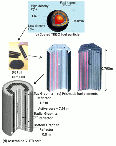
Figure 7. TRISO particle, fuel compact, and a prismatic fuel element or assembly, and cross-sectional view of an assembled Very High Temperature Reactor (VHTR).11-14
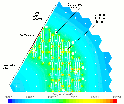
Figure 8. Calculated temperatures in a radial cross section of a full height 1/6th VHTR core during nominal operation using STAR-CCM+ Commercial Software.
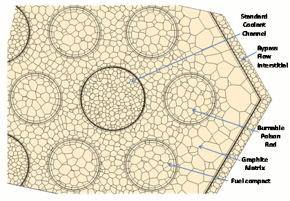
Figure 9. A close-up of the implemented numerical mesh grid in a prismatic VHTR fuel element with a helium bypass flow.
The mesher itself is a highly robust tool capable of automatically adjusting and repairing geometry based on specification from the user. STAR-CCM+ is also fully capable of parallelization for simulation runs and meshing, both on individual workstations and over a cluster (such as the one employed at the institute). The STAR-CCM+ code is also somewhat unique in that results can be accessed while the simulation is in progress without impeding or interrupting the simulation, giving the user real time feedback on the simulation. Examples include thermal-hydraulics analysis of a single fuel channel, full fuel element11 and full height 1/6th core of a prismatic Very High Temperature helium-cooled Reactors (VHTRs) (Figures 8 and 10). Figure 9 shows an example of the numerical mesh grid developed and implemented in the thermal-hydraulics analysis of a hexagonal, prismatic fuel element (Figure 6). Figurer 10 shows the numerical mesh grid developed and implemented in the thermal-hydraulics analysis of a full height 1/6 VHTR core.
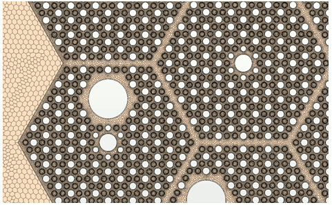
Figure 10. Numerical mesh grid implemented in the thermal-hydraulics analysis of a full height 1/6th VHTR core using STAR-CCM+ Commercial Software.
The Intitute also uses STAR-CCM+ to perform detailed 3-D thermal hydraulics analyses of space nuclear reactor concepts developed at ISNPS. The STAR-CCM+ code has been used to support multi-physics analysis of space nuclear reactors, externally coupling results with neutronics calculations performed using the Monte Carlo neutron transport code MCNPX. Detailed thermal-hydraulics calculations performed by STAR-CCM+ determine the spatial temperature profile inside the reactor core required for neutronics calculations at temperature, while MCNPX calculates the spatial thermal power profile in the fuel pins for input as a volume heat source in the thermal-hydraulics analysis. As the neutronics and thermal-hydraulics analyses depend on the results of the other, STAR-CCM+ and MCNPX are iteratively coupled together. This allows for detailed 3-D reactor analysis and design optimization. The ISNPS used this STAR-CCM+/MCNPX coupling to optimize the design of the liquid metal cooled Sectored Compact Reactor for lunar surface power (SCoRe-N) capable of supplying 40 kWe to a crewed outpost for more than 20 years (Figure 11). The core of the SCoRe-N is divided into six hydraulically independent sectors to avoid a single point failure in case one of the six sectors suffers a loss of the liquid NaK-78 coolant. Figure 12a shows a section view of one of the six core sectors in the SCoRe-N5 reactor operating at its full nominal power of 1 MWth. STAR-CCM+ is also used to model heat removal from a core sector in case of a loss of coolant, simulating conduction and radiation heat transfer within the sector voided of liquid NaK-78 coolant to the adjacent functioning sectors (Figure 12b).
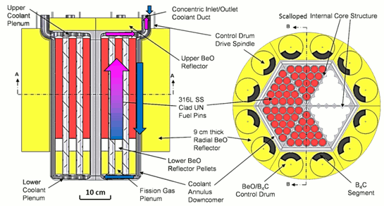
Figure 11. Cross-sectional views of the SCoRe-N5 design with coolant flow path detailed in section B-B.
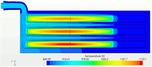
Figure 12a. Calculated temperatures at symmetry plane in SCoRe-N5 reactor with cusped cladding at 1 MWth.
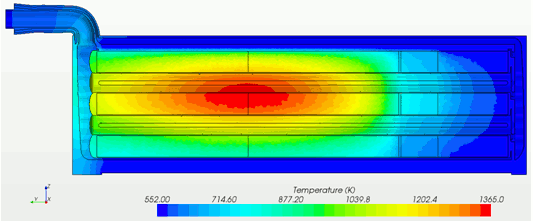
Figure 12b. Calculated temperatures at the symmetry plane in the sector with cusped cladding experiencing a loss of coolant at 166.6 kWth.
- 11. Travis, B.W and El-Genk, MS, "Numerical simulation and turbulent convection heat transfer correlation for coolant channels in a VHTR", J. Heat Transfer Engineering 2012; (in press).
- 12. Kiryushin, AI, Kodochigov, NG, Kouzavkov, NG, Ponomarev-Stepnoi, NN, Gloushov, ES, Grebennik, VN. "Project of the GT-MHR high-temperature helium reactor with gas turbine". J. Nuclear Engineering and Design 1997; 173: p. 119 -129.
- 13. MacDonald, P., et al., "NGNP preliminary point design - results of initial neutronics and thermal-hydraulic assessment", INEEL/EXT-03-00870 Rev. 1, 2003.
- 14. LaBar, M. P., et al., "The gas-turbine modular helium reactor," J. Nuclear Future 2004; 43 (3): 165 - 175.
- 15. Schultz, R. R, et al., "Next generation nuclear plant-design methods development and validation research and development program plan", INEEL/EXT-04-02293 Rev. 0, 2004.
 Back to The Top
2. COMSOL Multiphysics
COMSOL is a commercial software package that uses the finite element scheme to numerically solve not only single physics, but also multi-physics problems in engineering applications. Multiphysics modules include fluid flow, heat transfer, structural mechanics, chemical, and others. COMSOL Multiphysics provides very convenient environment by integrating all modeling process into one package from building geometries (2D and 3D), meshing, defining user equations, to visualizing and exporting results. COMSOL Multiphysics also supports parallel computing, allowing users to effectively solve large engineering problems by distributing multiple jobs to separate nodes of a cluster computer to overcome the memory challenge associated with commercial finite element packages.
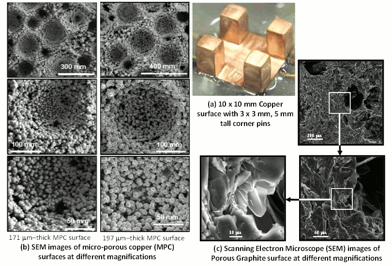
Figure 13a. Surfaces investigated for enhancing nucleate boiling of dielectric liquids (FC-72, HFE-7100 and PF-5060) for immersion cooling of high power computer chips. (Click for larger version)
Since 1990s, extensive experimental research has been performed on immersion cooling nucleate boiling of high power computer chips using dielectric liquids. Experiments investigated various surfaces measuring 10 x 10 mm in footprint. These surfaces include plane copper with various roughness and with corner pins, porous POCO graphite and micro-porous copper surfaces deposited using electrochemical deposition at a high current density. Experiments also investigated the effects of surface orientation from upward-facing (0o inclination) to downward-facing (180o inclination) on nucleate boiling heat transfer and the Critical Heat Flux (CHF). Figure 13a shows photographs of some of the surfaces investigated for enhancing nucleate boiling of the dielectric liquids PF-5060, FC-72 and HFE-7100.16-20

Figure 13b. Results of performed full 3-D thermal analyses of copper spreaders with micro-porous Cu or pins for cooling a 10 x 10 underlying computer chip with central hot spot, using COMSOL multi-physics code. Dissipated heat is removed from spreader surface by saturation boiling of PF-5060 dielectric liquid.21-22
In practical applications of immersion cooling of high power computer chips, heat spreaders with surfaces for enhancing nucleate boiling could be utilized to increase the removal rate of the thermal power dissipation by the underlying chip and mitigate the effect of hot spots. Numerical analyses of theses spreaders with a micro-porous copper surface and copper pins 3 x 3 in cross-section and 2- 5 mm tall have recently been performed using the COMSOL Multiphysics commercial software. Some of the results obtained are shown in Fig. 13b.21,22
A 3-D numerical thermal analysis has been carried out using COMSOL 4.0 to investigate the thermal performance of planar copper and copper spreaders with MPC surface. The MPC spreader are comprised of copper substrate and a MPC surface of 10's of microns thick for cooling a 10 x 10 mm underlying chip with central hot spot (Fig. 13b). The chip is assumed to have different hot spot areas with variable heat flux ratio. The effect of thermal interface material between the chip and the heat spreaders is also investigated. COMSOL results have been validated successfully against those obtained by ANSYS - finite elements commercial software for planar copper spreaders and copper spreaders with porous graphite surface.23,24 The total thermal power removed, the foot print area, spatial distribution of the surface temperatures of the spreaders and surface temperature distribution of the underlying chip are calculated (Fig. 13b).
- 16.El-Genk, M. S. and H. Bostanci, "Combined Effects of Subcooling and Surface Orientation on Pool Boiling of HFE-7100 from a Simulated Electronic Chip," J. Experimental Heat Transfer, 16, 2003, 281-301.
- 17.El-Genk, M. S. and J. L. Parker, "Enhanced Boiling of HFE-7100 Dielectric Liquid on Porous Graphite," J. Energy Conversion and Management, 46, 2005, 2455 - 2481.
- 18.Parker. J. L. and M. S. El-Genk, "Enhanced Saturation and Subcooled Boiling of FC-72 Dielectric Liquid," Int. J. Heat and Mass Transfer, 48(18), 2005, 3736 - 3752.
- 19.El-Genk, M. S. and Ali, A. F., "Enhanced Nucleate Boiling on Copper Micro-porous Surfaces," Int. J. Multiphase Flow, 36, 2010, 780 - 792.
- 20.El-Genk, M. S. and Ali, A. F., "Enhancement of Saturation Boiling of PF-5060 on Micro-porous Copper Dendrites Surfaces," J. Heat Transfer, 132, 2010, 071501-1 - 071501-9.
- 21. Ali, A. F. and M. S. El-Genk, "Spreaders for Immersion Nucleate Boiling of a Computer Chip with a Central Hot Spot," J. Energy Conversion and Management, 53, 2012, 259-267.
- 22. Ali, A. F. and M. S. El-Genk, "Numerical Analysis of Spreaders with an Enhancing Nucleate Boiling Surface for Immersion Cooling of Chips with Central Hot Spots," Proc. 13th Intersociety Conference on Thermal and Thermomechanical Phenomena in Electronic Systems (ITherm 2012), San Diego, CA, 2012.
- 23. El-Genk, M. S, H. H. Saber, and J. L. Parker, "Efficient Spreaders for Cooling High Performance Computer Chips," J. Applied Thermal Engineering, 27, 5-6, 2007, 1072 - 1088.
- 24. El-Genk, M.S. and H. H. Saber, "Composite Spreader for Cooling Computer Chip with Non-Uniform Heat Dissipation," IEEE Transactions on Components and Packaging Technologies, 31(1), 2008, 165 - 172.
Micro-droplets Emulsion Simulation
An emulsion is a mixture of two immiscible liquids in which one liquid in the form of droplets is dispersed in a continuous phase of the second liquid. Emulsions are encountered in chemical; petroleum; energy; pharmaceutical; food processing and cosmetics industries and used in medical procedures; drug delivery; polymerization processing; microanalysis; extraction processes and microsystems. Emulsions of mono-disperse micro-drops have been the subject of extensive investigations by numerous investigators. The aim has been to generate mono-disperse droplets of controllable sizes, ranging from a fraction to 10's of microns, at high frequencies. Conventional methods to produce emulsions involve injecting a liquid at a constant flow rate through an orifice or a capillary tube into a continuous immiscible liquid that is quiescent or dynamically inactive. These methods are inefficient because the bulk of the dispersed liquid is not used. In addition, the production rates of disperse droplets are relatively low and the emulsions are highly poly-disperse. To overcome some or all these limitations, recent techniques of membrane extrusion, micro-thread generation and viscoelastic shear have been proposed. Although more effective, each technique has some inherent limitations. For example, the poly-dispersity in the emulsion produced using membrane emulsification is ~ 10% of the average drop size, and as much as 16% in production condition using the viscoeleatic shear technique. A good control of the size, production frequency and the dynamics of forming disperse droplets, is achieved using co-flowing immiscible liquids (Fig. 14). This method not only provides better control of the droplet volume, but also produces highly mono-disperse emulsions. The forming droplets of disperse liquid at the tip of the inner micro-tube, grow, deform and eventually detach, or pinch off in a cyclical fashion. The formation dynamics of the droplets and the effects of the various controlling parameters have been investigated using COMSOL multi-physics code.
For co-flowing immiscible liquids in co-axial micro-tubes, two mechanisms of forming disperse droplets have been observed experimentally and predicted numerically. These are: (a) dripping, in which the forming droplet detaches directly off the tip of the inner micro-tube, and (b) jetting, in which the forming droplet detaches at the end of an extended thread or filament of the disperse liquid, some distance downstream from the tip of the inner micro-tube. The highly mono-disperse emulsion produced by the first mechanism prevails at low flow rates of disperse and continuous liquids. By contrast, the forming emulsions in the jetting regime at high liquids flow rates could be highly poly-disperse. For both mechanisms, increasing the flow rate of the continuous liquid decreases the size and increases the forming frequency of the droplets. In these mechanisms, there is a great degree of control on the operating parameters for producing the droplets, owing to the large interfacial area between the two, co-flowing immiscible liquids. The formation of mono-disperse droplets in the dripping regime evolves in three successive stages: (a) steady growth; (2) deformation and necking; and (3) detaching or pinch off (Fig. 14a -14c).
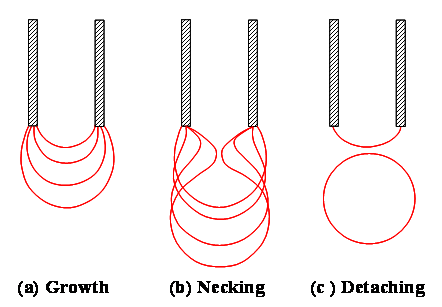
Figure 14. Growth, necking and detaching (or pinch-off) of a disperse droplet at the tip of a micro-tube in a continuous co-axial flow of an immiscible liquid.
The formation dynamics of disperse droplets in a system of two co-flowing immiscible liquids depend on many parameters, which are easily controlled in an experiment or industrial production. These are the average flow rates (or injection velocities), dynamic viscosities and densities of the continuous and disperse liquids; the diameters of the co-axial micro-tubes and the interfacial tension. Numerical simulations of the formation of disperse droplets in a system of co-flowing immiscible liquids in coaxial micro-tubes have used different numerical methods to solve the transient Navier-Stokes equations of the liquids, subject to the momentum jump condition at the interface. These simulations track the growth, surface topology, necking and the eventual pinch off of the disperse droplets.
In the dripping regime the drag force by the continuous liquid flow onto the interface with a growing disperse droplet causes necking and eventual pinch off of the droplet. In this regime, a precise control of the size and frequency of the forming droplets is possible by varying the flow rates of the co-flowing liquids. Forming either mono-disperse or poly-disperse droplets in the dripping regime depends on the flow rates and properties of the continuous and disperse liquids, the diameters of the co-axial micro-tubes, and the interfacial surface tension.
Numerical simulations are being carried out at the Institute for Space and Nuclear Power Studies, university of New Mexico, to investigate the dynamics and controlling parameters of forming micro-droplets of a disperse liquid in a continuous immiscible liquid, co-flowing in a co-axial micro-tube (Fig. 15). These simulations investigate the contributions of various parameters affecting the formation dynamics and frequency and the radius of disperse droplets. The simulations solve the transient, 2-D axisymmetric Navier-Stokes equations in the computational domains of the co-flowing liquids and the advection equation of the interface between the two immiscible liquids, subject to the prevailing momentum jump condition at the interface. The numerical solution of these equations uses a finite element method based on the capabilities of the COMSOL Multiphysics, version 4.0.
The numerical simulations track: (a) the disperse droplet transient growth and eventual pinch off; (b) the evolving interface between the co-flowing liquids during the initial formation and growth of the disperse droplet, and (c) the induced liquid circulation inside the droplet at different stages of growth to an eventual pinch off. The obtained numerical results of the effects of different controlling parameters are used to develop empirical correlations for the dimensional radius and the formation frequency of the disperse droplets in terms of the capillary number of the continuous liquid and the ratios of Reynolds numbers and diameters of micro-tubes of the co-flowing immiscible liquids.
Figure 15 depicts the formation of a disperse droplet of an incompressible and Newtonian liquid at the tip of a micro-tube with an inner radius, Rd, in a co-flowing immiscible, incompressible and Newtonian liquid in a concentric micro-tube of a larger radius Rc (Rc > Rd). The disperse liquid has a dynamic viscosity, and a density, and the continuous liquid has a dynamic viscosity, and density. The numerical analysis investigated the effects of the different parameters on the formation frequency and radius of disperse droplets in the dripping regime. These parameters are interfacial surface tension and velocities, viscosities, and radii of micro-tubes for the co-flowing immiscible liquids.
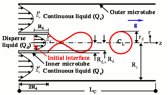
Figure 15. Schematic of a disperse droplet forming in a co-flowing immiscible liquid in a larger co-axial micro-tube.
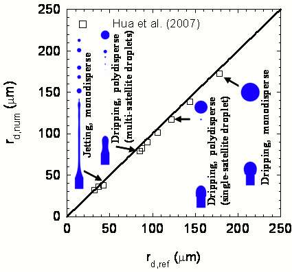
Figure 16. Comparison of present numerical calculations of radius of disperse droplets [25] with those of Hua et al. [26] for co-flowing immiscible liquids.
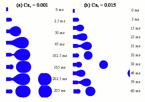
Figure 17. Images of cyclical formation of mono-disperse droplets in dripping regime at two different values of capillary number of continuous liquid, Cac [25].
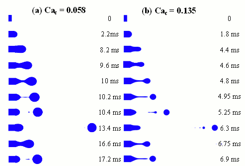
Figure 18.Successive images of the cyclical formation of poly-disperse droplets in dripping regime at two different values of Cac [25].
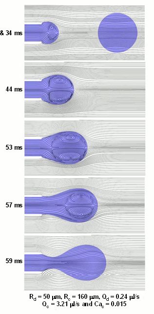
Figure 19.Flow circulation inside disperse droplet, during its stages of formation, clockwise and counter-clockwise vortices [25].
The images in Fig. 19 (to the right of the page) are of the flow fields inside a mono-disperse droplet and of the surrounding co-axial continuous liquid at different times during the formation cycle of the droplet, at Cac = 0.015 [25]. As soon as a disperse spherical pendent appears at the tip of the inner co-axial micro-tube, a pair of clockwise and counter-clockwise vortices forms inside the liquid pendent. This is shown in Fig. 19 after 4 and 34 ms into the transient or formation cycle of the disperse droplet. The extent of the internal liquid vortices increases as the droplet continues to grow, are driven by the change in the local curvature (or surface tension force) along the surface of disperse droplet.
- 25. In-Hwan Yang and M. S. El-Genk, "Emulsion Formation in Dripping Regime of Co-Flowing Immiscible Liquids in Co-Axial Mictotubes," International Journal of Micro-Nano Scale Transport, 2 (1), 2011, 57 - 83.
- 26. Hua, J., Zhang, B. and Lou, J., "Numerical simulation of microdroplet formation in coflowing immiscible liquids," AIChE Journal, 2007, 53(10), 2534 - 2547.
Back to The Top3.ANSYS Commercial Software
ANSYS is a general purpose finite element modeling package for numerically solving a wide variety of mechanical problems. These problems include: static/dynamic structural analysis (both linear and non-linear), heat transfer and fluid problems, as well as acoustic and electromagnetic problems. In the past, obtaining all of the simulation capabilities needed for complex and demanding modeling scenarios frequently meant combining several different software packages. ANSYS Multiphysics provides the analysis industry's most comprehensive coupled physics tool combining structural, thermal, CFD, acoustic and electromagnetic simulation capabilities into a single software product. ANSYS Multiphysics integrates the power of direct (matrix) and sequential (load vector) coupling to combine the appropriate "physical fields" required for accurate, reliable simulation results in applications ranging from cooling systems, power generation, to biotechnology and Micro Electro Mechanical Systems (MEMS).
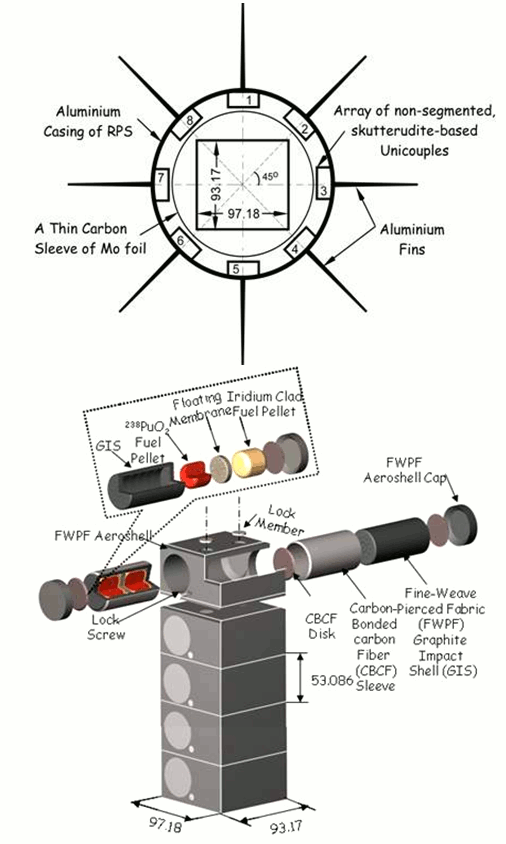
Figure 20. Skutterudite Thermoelectric Radioisotope Power System for generating 100 We for > 10 yrs in support of future NASA Planetary Exploration Missions (top); a stack of General Purpose Heat Source Modules with 238PuO2 Pellets (bottom). Each module generated a total of 250 Wth at Beginning of Life [27].
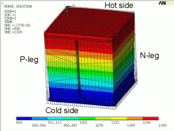
Figure 21. Temperature contours and displacements in a SiGe Thermoelectric unicouple of a Power Conversion Assembly of a Jupiter Icy Moon Orbiter Spacecraft.
The software easily simulates complex thermal-mechanical, fluid-structural and electrostatic-structural interactions, and includes the complete range of powerful ANSYS iterative, direct and eigenvalue matrix solvers. ANSYS Mechanical includes a full complement of nonlinear and linear elements, material laws ranging from metal to rubber, and the most comprehensive set of solvers available. It can handle even the most complex assemblies especially those involving nonlinear contact and is the ideal choice for determining stresses, temperatures, displacements and contact pressure distributions on all your component and assembly designs.
The UNM-ISNPS has developed and designed a novel, thermoelectric radioisotope power system for NASA's future space and planetary exploration missions (Fig. 20). This system will not only have a specific electric power greater than 12 We/kg, which is more than twice that of the state-of-the-art GPHS Radioisotope Thermoelectric Generators (which power the Voyager, Galileo and Ulysses probes), but also an overall efficiency greater than 14%. Such high conversion efficiency would halve the amount of plutonium dioxide fuel needed for a given electric power requirement. The proposed advanced power system couples novel, segmented thermoelectric unicouples, based on advanced thermoelectric materials developed at the Jet Propulsion Laboratory (JPL), to one or several standard General Purpose Heat Source bricks, and would be easily scalable to meet missions power requirement ranging from a few watts to hundreds of watts.
During the course of this work, it was necessary to create and incorporate new numerical elements and new routines in the very powerful ANSYS 5.7 finite elements software to extend the capabilities of the software for ultimately modeling the entire radioisotope power system as well as the experimental setup. ANSYS has also been used at UNM-ISNPS to perform thermo-mechanical analyses of non-segmented (Fig. 21) and segmented multicouples for RPSs.
- 27. El-Genk, M. S., H. H. Saber, and T. Caillat, "Efficient, Segmented Thermoelectric for Space Power Applications," J. Energy Conversion and Management, 44(11), 2003, 1755 - 1772.
Back to The Top4.MATLAB/SIMULINK
ISNPS has developed a Dynamic simulation Model (DynMo-TE) of Space Reactor Power Systems (SRPSs) [28] with Thermo-Electric (TE) conversion, and is currently developing the DynMo-CBC [29] for simulating the dynamic behavior of SRPSs with Closed Brayton Cycle (CBC) engines (Figs. 22-24) using the SIMULINK® platform (https://www.mathworks.com/products/simulink). This platform offers an interactive graphical environment that allows rapid development of library blocks of the system components, thus components can be easily replaced or exchanged with little effort. Each component block has a number of input and output ports, and the blocks interact with each other by simply connecting these ports. Other input parameters necessary for the component blocks to operate are easily implemented through a customizable window or "mask," or by loading an input or "script" file.
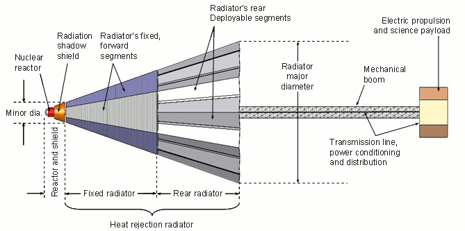
Figure 22. S4 gas cooled reactor - CBC space reactor power system, fully deployed [29]. This power system design avoids single point failures in reactor cooling and energy conversion and could generate 100 kWe for greater than 7 years [29].
Another advantage of SIMULINK® is that is does not require the development and optimization of numerical schemes to deal with steep transients and the strong couplings inherent of the physical model equations. Through its integration with MATLAB® (https://www.mathworks.com/products/matlab), SIMULINK® has immediate access to an extensive range of tools for numerical computation, time integration, algorithm development, and data visualization and analysis. In addition to significantly reducing the development time and effort, such simulation capabilities make is easy to investigate the effect of replacing different types and/or using different designs of the system components such as pumps, heat pipes, etc. on the dynamic operation of the SRPS. SIMULINK® is also particularly well suited for studying the startup of the SRPS in orbit, and associated control scenario, and for developing adaptive control strategies for use on board the autonomous spacecraft in response to: (a) changes in system parameter over the long operation lifetime, caused by fuel burnup and degradation in materials properties for example; and (b) unanticipated changes in environmental conditions, such as meteoroids impacts.
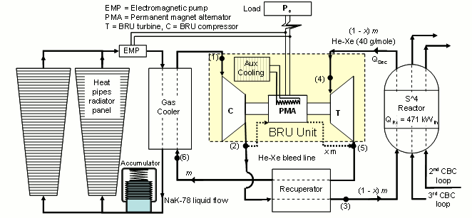
Figure 23. A layout of one CBC loop in the S4 gas cooled reactor and a closed Brayton cycle (CBC ) space reactor power system for generating 100 kWe for greater than 7 years [28].
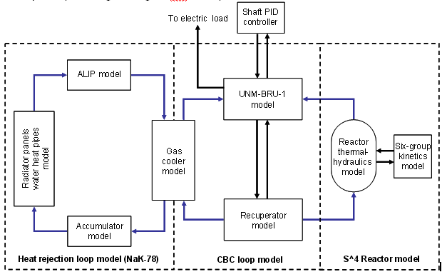
Figure 24. Building blocks of DynMo-CBC for S4-CBC space reactor power system [28].
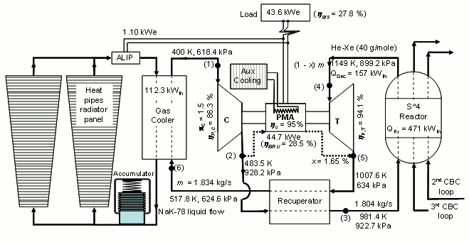
Figure 25. Full power, steady-state operation parameters in one of three loops of in the S4-CBC space power system [29].
At the system's steady-state full power operation delineated in Figure 25, each CBC loop rejects a total of 112.3 kWth to the circulating liquid NaK-78 in the heat rejection loop, to be equally rejected into space by two water heat pipe radiator panels. The corresponding specific mass of the UNM-BRU-1 is as small as ~1.16 kg/kWe and the Co-Sm permanent magnet of the BRU alternator is cooled below 500 K using an auxiliary heat pipes radiator. The bleed fraction of the He-Xe working fluid at the exit of the UNM-BRU-1 compressor, for cooling the rotating shaft, compressor and turbine disks and bearings and the electrical alternator, is 1.65% (or 30.26 g/s) (Fig. 25).
The S4 reactor's steady-state thermal power of 471 kWth is determined based on detailed thermal-hydraulic and CFD analyses, therefore increasing this thermal power requires redesigning the reactor and performing detailed
neutronics and thermal analyses. On the other hand, the power system's electrical power could be intermittently decreased below the nominal value of 130.8 kWe (Fig. 25), in order to meet
a specific power requirement profile for a space mission. This may be done in two ways:
(a) Lower the steady-state electrical power generated by the S4-CBC space power system by decreasing the thermal power of the reactor and the flow rate of the He-Xe reactor coolant
and CBC working fluid commensurate with the decrease in the reactor thermal power, while operating at the same compressor and turbine inlet temperatures of 400 K and 1149 K (Fig. 25)
and the UNM-BRU-1 (single shaft, CBC turbo-machine designed at the Institute for Space and Nuclear Power Studies [30]) at a shaft speed of 45 krpm; or
(b) Maintain the reactor's steady-state thermal power at its nominal design value 471 kWth and decrease the inlet temperature to the UNM-BRU-1 turbine to less than 1000 K,
while operating at the same compressor inlet temperature of 400 K and the UNM-BRU-1 shaft speed of 45 Krpm.
- 28. El-Genk, M. S. and J.-M. Tournier, "DynMo-TE: Dynamic Simulation Model for Space Reactor Power Systems with ThermoElectric Converters," J. Nuclear Engineering and Design, 236(23), 2006, 2501 - 2529
- 29. El-Genk, M. S., Tournier, J.-M., P., and Gallo, B. M., "Dynamic Simulation of a Space Reactor System with Closed Brayton Cycle Loops," J. Propulsion and Power, 26(3), 2010, 394 - 406.
- 30. Gallo. B. M, and M.S. El-Genk, "Brayton Rotating Units for Space Reactor Power Systems," J. Energy Conversion and Management, 50(9), 2009, 210 - 2232.
Back to The Top5. SOLIDWORKS / COSMOSWORKS
SolidWorks® is a 3-dimensional design and mechanical engineering software used under license from Solidworks Corporation. It has been used extensively in the design and analysis of the Sectored, Compact Reactor (SCoRe) developed at UNM-ISNPS, a liquid-metal cooled space power reactor which prevents single-point failure within its cooling loops, and maintains subcriticality in the case of a launch abort incident [32, 33]. Originally modeled in SolidWorks®, this SCoRe concept model was used to assist and verify geometry inputs for the neutronics codes MCNP5 and MCNPX. Since SolidWorks has the capability of entering physical properties for the structural materials in the SCoRe, such as density, the mass of the various components can be compared with the output from MCNP to verify the correct modeling of the system. SolidWorks® has also been helpful to ISNPS engineers in designing nuclear radiation shields and other space nuclear reactors, such as heat pipe-cooled reactors for which the main challenge is the routing of the relatively large number of reactor heat pipes around or through the radiation shield (Fig. 27), and their coupling to the energy conversion units in the space power system. The mechanical animation capability of SolidWorks® has also been used successfully to obtain snapshots of space reactor power systems with segmented and deployable radiation panels, at different times during the deployment process in space orbit.
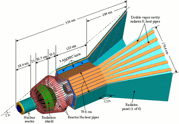
Figure 26. Isometric View of the Scalable AMTEC Integrated Reactor Space Power System (SAIRS-C) [34].
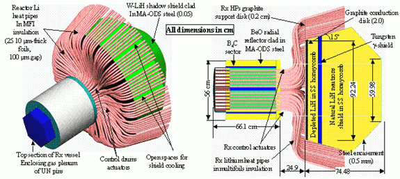
Figure 27. Cross-sectional and Isometric Views of the HP Reactor and the Radiation Shield designs developed at the University of New Mexico's Institute for Space and Nuclear Power Studies for the power system in Fig. 26 [32].
- 32. El-Genk, M.S., S. Hatton, C. Fox, and J.-M. Tournier, "SCoRe - Concepts of Liquid Metal Cooled Space Reactors for Avoidance of Single-Point Failure," Proceedings of Space Technology and Applications International Forum (STAIF-05), AIP Conference Proceedings No. 746, American Institute of Physics, Melville, NY, 2005, 473 - 484
- 33. Schriener, T. M. and M. S. El-Genk, "A Neutronics Analysis of Long-Life, Sectored Compact Reactor Concepts for Lunar Surface Power," J. Progress in Nuclear Energy, 53(1), 2011, 106 - 118
- 34. El-Genk, M. S. and JM. Tournier, "SAIRS"- Scalable AMTEC Integrated Reactor Space Power System," J Progress in Nuclear Energy, 45(1), 2004, 25-69.
Back to The Top